Drag and drop your ortho and dsm onto the project.
Click "Insert" when finished uploading
Expand CalPoint and select your calibration point.
Click viewpoint 3D
Use middle mouse to inspect point in relation to surface.
In this case you can see the point is floating above the surface.
Click here
Click "Point #6"
This is the current elevation of the point. Write this number down.
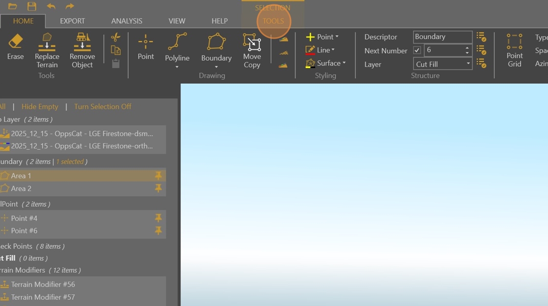
Click "TOOLS"
Click here
This the new elevation of your Calpoint. Write this number down and subtract it from the first number you wrote down. The result will be the value we input into the Z offset.
Enter the result of your 2 value's difference here, it will raise or lower the DSM based off this value. Keep in mind what you are trying to do. Am I trying to raise the DSM? or lower it. Make the decision to enter your result as a negative or positive number.
Press [[Return]]
Click "Point #6"
Click here
This number should match the first number you wrote down earlier.
Click here - Turn the ortho off
Your screen should now look like this.
Click "2025-12-01" in the timestep panel
Turn the ortho off here as well.
Click "2025-12-15" and "2025-12-01" back and forth to make sure that the current boundary captures everything in the terrain with major changes.
Click "2025-12-01"
If you conclude that you need to edit your Boundary to capture major terrain changes, expand your boundary layer.
Click the boundary you need to edit.
Click Edit Vertex
Click once on a line to add a vertex then drag to move it.
Or click and drag an existing vertex to edit.
Continue until boundary is sufficient.
Click "2025-12-15"
Turn the ortho back on.
Middle click here
Click "HOME"
Click Layer Dropdown
Select the "Terrain Modifiers" layer.
You are now ready to begin removing 3D objects that influence the DSM from the project. (Terrain Flattening)
Click Remove Object
Click on a object that is showing up in the 3D model that you do not want to effect the overall report. Mostly man made objects, tractors, excavators, vehicles, portable generators etc.
Here it is an excavator, click on the excavator and VS will automatically flatten that object.
This is the end result.
Here is a truck - click on it to flatten.
Inspect the entire project boundary for examples like these until there are none remaining.
Click SAVE when terrain editing is finished.
If you have other checkpoints such as the pink ones shown here, inspect them to make sure everything is lining up.
This is an example of what you would expect to see if everything is lining up well. If the point is floating or completely under the ground ask for assistance from a supervisor.
Click the previous timestep from the timestep panel.
Expand and ensure that your terrain modifiers are all checked and on.
Click the current timestep from the timestep panel.
Expand and ensure that your terrain modifiers are all checked and on here as well.
Click "Area 1" or your first project boundary (you may only have 1).
Layer dropdown.
Select Cut Fill
Click "TOOLS"
Click the "Use" dropdown. This will tell VS what section or tool we want to use to compare against.
Select Timestep - This tells VS we want to compare between timesteps.
Click "Compare To" dropdown.
Click the previous project in the timestep. Currently you should be in 2025-12-15 so we want to select 2025-12-01 for our comparison.
Click "Cut/Fill" button.
Expand the Cut Fill Layer.
Click "Area 1" or whatever your Boundary was named here.
Inserting a value here will tell VS to display everything greater than this value. We like to start with .25 and go as high as 1.00. the goal is to capture as much change as we can without making the report look too busy or distracting.
Notice how almost everything within the boundary has color? We do not necessarily want that. It does not communicate the message that this report is intended for.
Change the min. Cut/Fill to .5 to observe the difference.
Notice the difference? This better shows the customer what material was moved and where to without being to confusing.
Now click the 2D view.
Now we are going to do a spot check. You want to try and locate a spot that has remained undisturbed between the 2 reports. In this case we will use this spot shown here.
Click "HOME"
Click the Point tool.
Click here
Click the Pin icon on your placed point. This will carry it over to our previous timesteps.
Click "Point #47"
Click "2025-12-01"
Ensure your Ortho is turned back on for this.
Click 3D viewer.
As with the checkpoints we want to make sure THIS point is not floating off in space somewhere. It should be right on top of the ground. When you have verified this is the case right click on your point on the Layers panel and delete it.
Click "Yes"
Click back to your current timestep in this case "2025-12-15"
Click back to 2D viewer.
Click "Area 1"
Make sure the format is set to .tif then click "Export Image".
Click "Clients"
Double-click "Company Name"
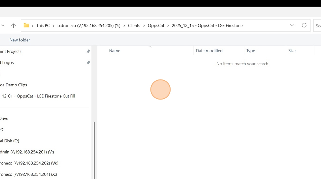
Name the folder with the format using the project capture date "YYYY_DD_MM - Company Name - Site Name"
Double-click "Name"
Right click "Items View"
Click "Folder"
Name the folder VS Exports
Double-click "Name"
Click "File name:"
Name the file with the same format as before "YYYY_DD_MM - Company name - Site name".
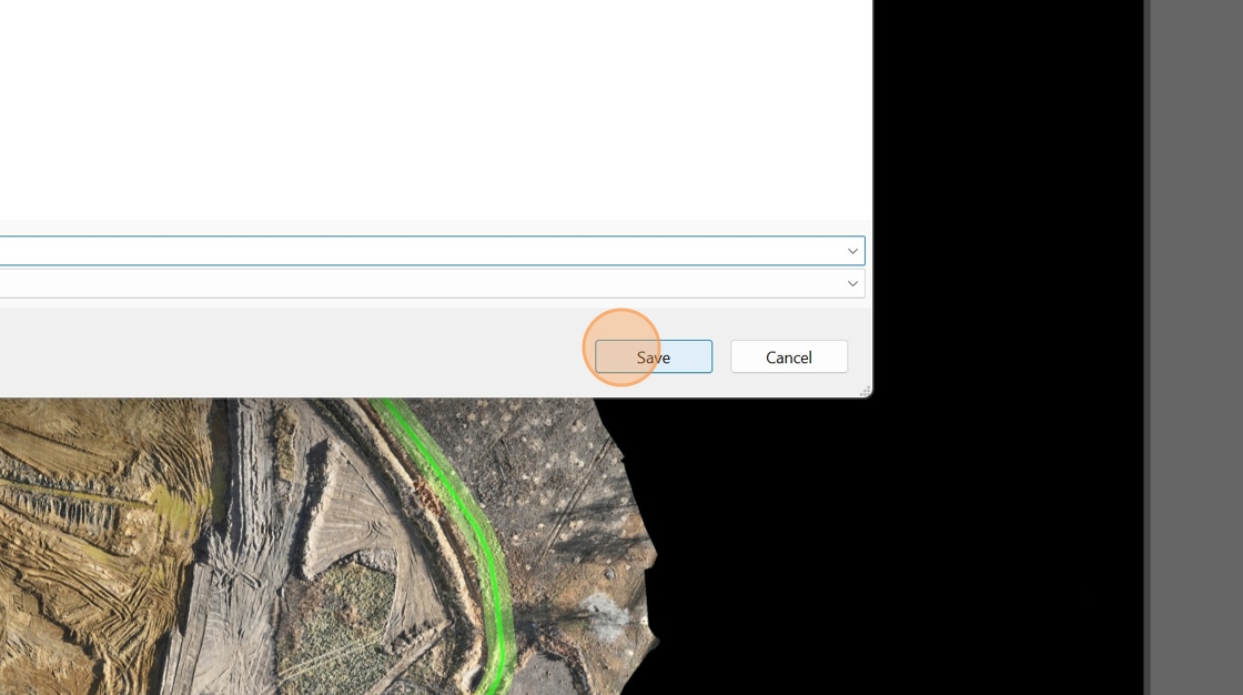
Click "Save"
Click "Area 1"
Open "Snipping Tool"
Click "NEW"
Click and Drag over the Selection box at the bottom right. This will capture the values for Area 1 in an image that we can save.
Click "Save"
Click "txdroneco (\192.168.254.205) (Y:)"
Double-click "Clients"
Double-click "Company Name"
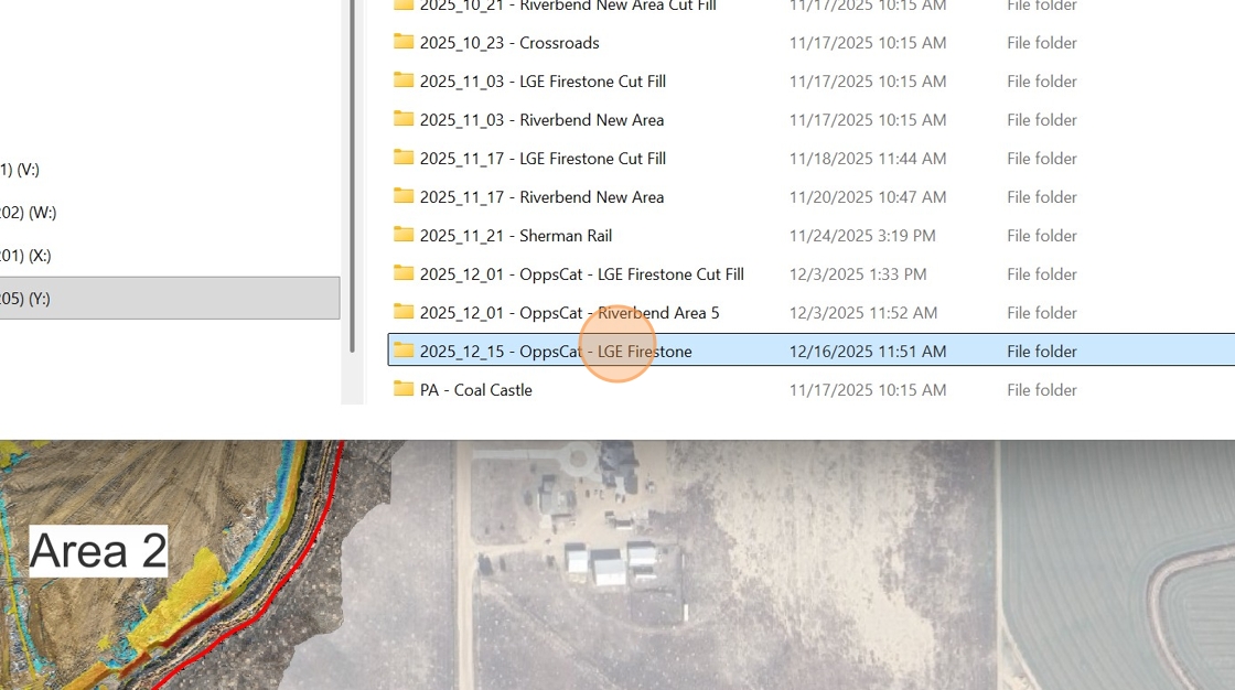
Double-click your project folder.
Click "File name:" rename to "Values - Area 1"
Click "Save"
Click "2025-12-15"
Repeat Steps 1-24 if you have a second area within the same project to report on.
Enable your terrain modifiers layer.
Enable your Area 2 cut fill layer
Click "Area 2"
Click the "refresh" button.
Open "Snipping Tool" again and capture the Area 2 Values. Save them just as before as "Values - Area 2" in the project folder.
If you had to edit a boundary within your project you will need to export the new boundary to be used in producing the report. See below. Make sure everything EXCEPT the boundary is turned off before exporting.
Check/Select Area 2
Make sure the format is set to .shp then Click here.
Navigate to your the "VS Exports" folder you created earlier and save as "Boundary Area 2".
Click "Save"
Save your VS project.
Open QGIS.
Click "Project"
Click "Open…"
Double-click "Previous project name"
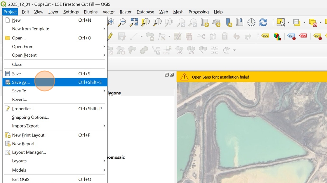
Click "Project"
Click "Save As…"
Change the date in the file name to the current capture date. Leave the company and site name as it.
Click "Save"
Navigate to the VS exports folder we created earlier for this project. Typically in Clients/Company Name/Project Date/Vs Exports.
Double-click "Name"
Double-click "Name"
Double-click "Name"
Drag and drop the TIF files into QGIS.
Drag and drop the SHP file into QGIS.
Right click the previous capture's boundary.
Click Copy style, then "All Style Categories"
Right click the new capture boundary that you dropped in to QGIS.
Click Paste Style then click "All Style Categories"
Right click the old boundary then click "Remove Layer…"
Click "OK"
Remove the old layers from the project. Right click.
Click "Remove Layer…"
Click "OK"
Right click here
Click "Remove Layer…"
Click "OK"
Right click here
Click "Remove Layer…"
Click "OK"
Click and drag to arrange your layers to match the format below.
Navigate to file explorer and find the Orthophoto export from the Pix4Dmatic project.
Click "txdroneco (\192.168.254.201) (X:)"
Double-click "Pix4Dmatic Archive"
Double-click the month folder the P4Dm project is saved in.
Double-click "Project Name"
Double-click "Exports"
Drag and drop the ORTHOmosaic into your open QGIS project.
Ensure the Orthomosaic is on the bottom layer and click "Save".
Click "Project"
Click "Side Look"
Click here
Edit the dates to match the current project capture dates.
Open File explorer and navigate to the VS Exports folder containing the screenshots for the area values you saved earlier.
Click "Clients"
Double-click "Name"
Double-click "Name"
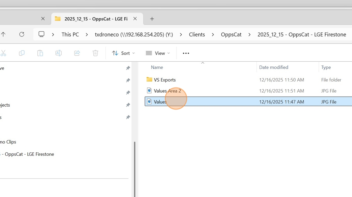
Double-click "Values" & "Values Area 2"
Using your screenshots as reference update the Cut, Fill, and Net Fill, values here.













No comments to display
No comments to display