
Setting Up Your RTKUSA Base
01 Getting Started
What You’re Setting Up
Your RTKUSA Base Station is the foundation of your accuracy. Once installed correctly, it continuously transmits correction data to improve positioning down to the centimeter level.
What’s in the Box
- Multi-band GNSS Receiver
- Survey-grade GNSS Antenna
- Antenna Cable (~9m)
- WiFi Antenna
- USB-C Power Cable
- Mounting Hardware
02 Antenna Installation
Why This Matters
If you get this wrong, nothing else matters.
Placement Requirements
Locate a sturdy location where you can mount the antenna. You will need to make sure there are no obstructions from the horizon 360 degrees around the antenna. The peak of your roof is often an ideal location.
Mount the antenna using the included mounting pole and bracket, then connect one end of the 9m antenna cable to the antenna.
Run the other end of the antenna to the base station.
- Full 360° open sky view
- No obstructions (trees, buildings, metal structures)
- Mounted as high as possible
Best option: Roof peak or elevated mast
Prepare the Base Station
Remove the red plastic cap from the WiFi-BT input and connect the WiFi antenna.
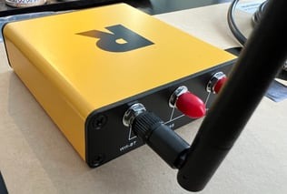
Next, remove the red plastic cap for "GNSS+" and connect the smaller end of the antenna cable.
Next, plug in the USB-C cable and power the device with any USB charger that provides at least 1 amp.
It can take up to 7 days to get a precise point once the RTKUSA Base is installed and configured. A "FIX" will not be available until this process is complete. If you ordered your RTKUSA Base with RTK then once the fix is obtained you will receive your RTKUSA Base credentials on your RTKUSA Cloud Account.
Installation Steps
- Mount the antenna using included hardware
- Connect antenna cable to antenna
- Route cable to base station
Pro Tip: Signal quality = performance.
Bad placement = bad corrections = wasted time.
03 Base Station Setup
Connect Hardware
- Attach WiFi antenna
- Connect GNSS antenna cable
- Plug in USB-C power (minimum 1A)
Power On
Switch your RTKUSA Base unit to the "ON" position using the small slide switch. The left red LED (Power) will turn solid.
The right green LED (WiFi Internet) should be blinking slowly.
The middle orange LED (PPS) will be off and activated later.
The device is now in the “Access Point Mode” (AP Mode).
LED Indicators
- Red (Power): Solid
- Green (WiFi): Blinking
- Orange (Satellite Sync): Off initially
The unit is now ready for configuration.
LED |
FUNCTION |
STATUS |
| RED | Power | SOLID: when powered |
| ORANGE | PPS (Pulse Per Second) | BLINKING (1s): antenna sees satellites |
| GREEN | WiFi / Internet (2Ghz) |
BLINKING (slow): Access Point Mode, Used for configuring Internet Connection.
BLINKING (fast): Attempting to connect to Internet via configured SSID and Password
SOLID: Internet is connected. |
For debugging, the USB-C can be used as a serial communication port. Note: we recommend using the provided WiFi antenna, as during testing we have seen issues with other WiFi antennas.
04 Connect to the Base Station
Step 1: Join the Network
- Network Name: MobileCM
- Password: Device serial number
“No Internet” message is normal.
Step 2: Open Setup Page
Go to: 192.168.4.1
Step 3: Enter Network Info
Required Inputs
- SSID: Your WiFi name (must be 2.4GHz)
- Password: Your WiFi password
- Miner Key: Unique name (12–18 characters)
Example: DFW_Base01
Save Settings
- Green LED should turn solid = success
- Blinking = failed connection
05 Confirm Connection
Access Device on Network
- Log into your router
- Find device named: espressif
- Note IP address (192.168.x.x)
- Enter IP into browser
Login
Use your Miner Key
06 System Active
Confirmation
When setup is complete:
- Status: TRANSMITTING
- Green LED: Solid
Your base station is now sending correction data.
07 Accuracy Lock Period
What to Expect
Your base station needs time to establish a precise position.
- Estimated time: 5–7 days
- No fixed solution until complete
Why This Matters
This process enables:
- Repeatable accuracy
- Reliable RTK corrections
- Survey-grade results
Skipping this step leads to poor data.
08 Troubleshooting
WiFi Issues
- Confirm network is 2.4GHz
- Re-enter password carefully
- Avoid special characters
Reset Device
Weak Performance
Check antenna placement:
- Must have clear sky view
- Elevation improves results
09 Signal Quality (SNR)
Acceptable Range
- Ideal: 37–45
- Below 32: Not usable
What Affects Signal
- Trees
- Buildings
- Metal structures
- Poor placement
Recommendation
Install antenna in open sky for best performance
10 What Happens Next
After Stabilization
Once your base station is fully established:
- It becomes part of a correction network
- Provides consistent high-accuracy positioning
- Improves field efficiency and reliability
Outcome
- Faster workflows
- Better deliverables
- Increased confidence in your data